


Contaminant Comparison Chart

For a complete list of contaminants that PUR filters reduce, please view our Performance Data Sheets here.


PUR & PUR PLUS FAUCET FILTERS
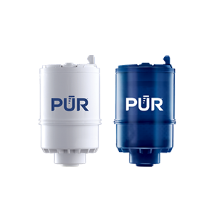
RF3375/RF9999

View Filters

PUR PLUS PITCHER FILTERS
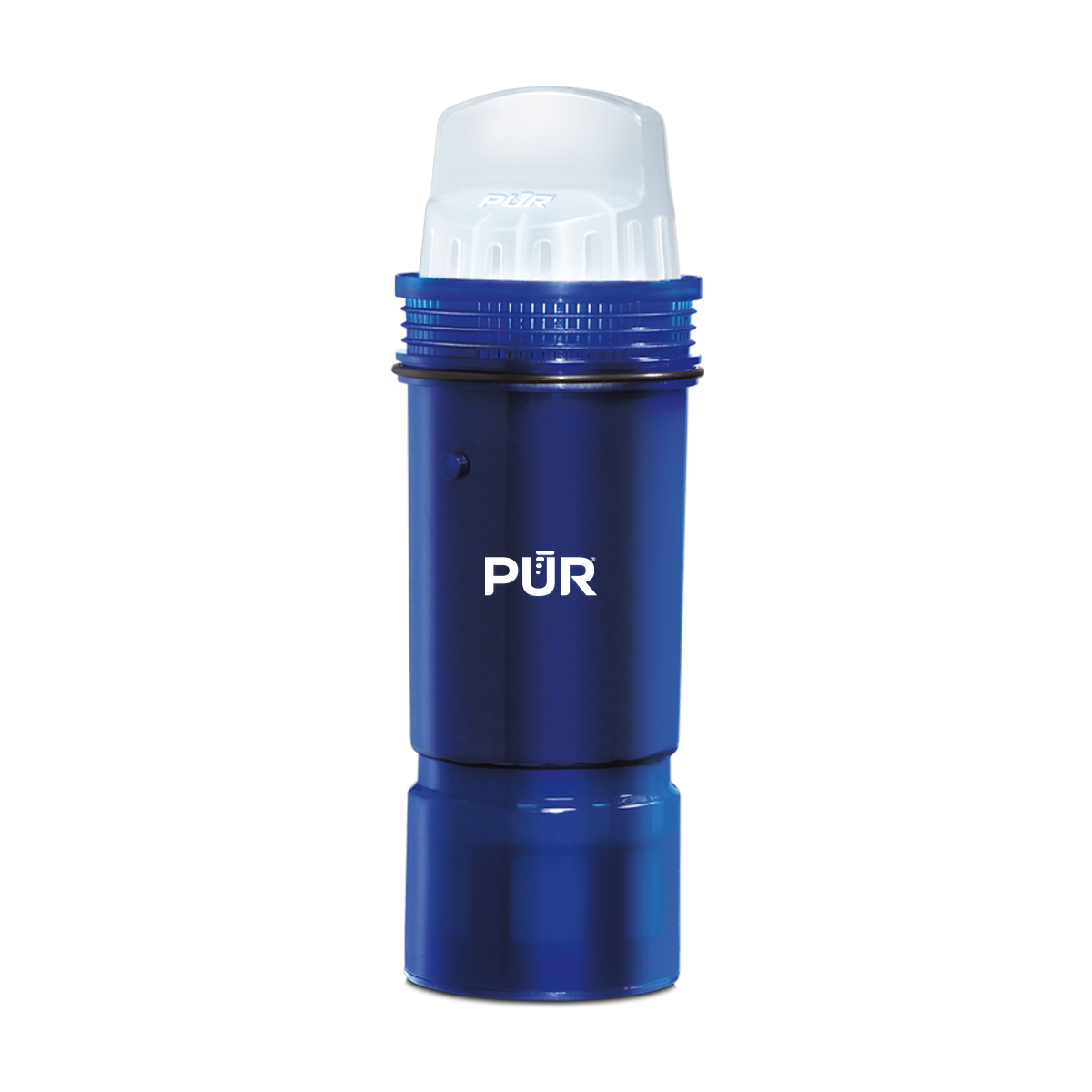
PPF951K

View Filter

PUR BASIC PITCHER FILTERS
PPF900Z

View Filter


Vs. Brita*

Lead ✓ ✓
Microplastics ✓ ✓
Mercury ✓ ✓ ✓
Chlorine Taste & Odor ✓ ✓ ✓
DEET ✓
TTHM ✓

PUR’s Filtration Systems Are Certified By NSF And WQA For Their Contamination Reduction. WQA certifications as of 5/27/21 for Faucet filter models RF-3375 and RF-9999.

¹ Certified to reduce 10X more chemical and physical substances than Brita’s® leading pitcher filter.
² Certified to reduce 3X more chemical and physical substances than Brita’s® leading pitcher filter.
³ Certified to reduce 2X more chemical and physical substances than Brita’s® leading pitcher filter.
*Versus best-selling Brita® pitcher filter OB03. Brita® is a trademark of Brita LP.
**Like other leading brands, PUR does not filter microbes. As of 3/1/23 Brita® and ZeroWater® were not certified to filter microbes. Brita® is a trademark of Brita LP. ZeroWater® is a trademark of Zero Technologies, LLC..
 

PUR & PUR PLUS FAUCET FILTERS


PUR & PUR PLUS FAUCET FILTERS
RF3375/RF9999

View Filters


Vs. Brita*

Lead ✓
Microplastics ✓
Mercury ✓
Chlorine Taste & Odor ✓
DEET ✓
TTHM ✓

PUR’s Filtration Systems Are Certified By NSF And WQA For Their Contamination Reduction. WQA certifications as of 5/27/21 for Faucet filter models RF-3375 and RF-9999.

¹ Certified to reduce 10X more chemical and physical substances than Brita’s® leading pitcher filter.
² Certified to reduce 3X more chemical and physical substances than Brita’s® leading pitcher filter.
³ Certified to reduce 2X more chemical and physical substances than Brita’s® leading pitcher filter.
*Versus best-selling Brita® pitcher filter OB03. Brita® is a trademark of Brita LP.
**Like other leading brands, PUR does not filter microbes. As of 3/1/23 Brita® and ZeroWater® were not certified to filter microbes. Brita® is a trademark of Brita LP. ZeroWater® is a trademark of Zero Technologies, LLC..


PUR PLUS PITCHER FILTERS


PUR PLUS PITCHER FILTERS
PPF951K

View Filter


Vs. Brita*

Lead ✓
Microplastics ✓
Mercury ✓
Chlorine Taste & Odor ✓
DEET
TTHM

PUR’s Filtration Systems Are Certified By NSF And WQA For Their Contamination Reduction. WQA certifications as of 5/27/21 for Faucet filter models RF-3375 and RF-9999.

¹ Certified to reduce 10X more chemical and physical substances than Brita’s® leading pitcher filter.
² Certified to reduce 3X more chemical and physical substances than Brita’s® leading pitcher filter.
³ Certified to reduce 2X more chemical and physical substances than Brita’s® leading pitcher filter.
*Versus best-selling Brita® pitcher filter OB03. Brita® is a trademark of Brita LP.
**Like other leading brands, PUR does not filter microbes. As of 3/1/23 Brita® and ZeroWater® were not certified to filter microbes. Brita® is a trademark of Brita LP. ZeroWater® is a trademark of Zero Technologies, LLC..


PUR BASIC PITCHER FILTERS


PUR BASIC PITCHER FILTERS
PPF900Z

View Filter


Vs. Brita*

Lead
Microplastics
Mercury ✓
Chlorine Taste & Odor ✓
DEET
TTHM

PUR’s Filtration Systems Are Certified By NSF And WQA For Their Contamination Reduction. WQA certifications as of 5/27/21 for Faucet filter models RF-3375 and RF-9999.

¹ Certified to reduce 10X more chemical and physical substances than Brita’s® leading pitcher filter.
² Certified to reduce 3X more chemical and physical substances than Brita’s® leading pitcher filter.
³ Certified to reduce 2X more chemical and physical substances than Brita’s® leading pitcher filter.
*Versus best-selling Brita® pitcher filter OB03. Brita® is a trademark of Brita LP.
**Like other leading brands, PUR does not filter microbes. As of 3/1/23 Brita® and ZeroWater® were not certified to filter microbes. Brita® is a trademark of Brita LP. ZeroWater® is a trademark of Zero Technologies, LLC..


How Does the Vacuum Brazing Process Work?

Vacuum brazing joins metal components by heating them in a controlled vacuum with a filler metal between their surfaces. The filler melts and flows into the joint, while the base materials remain solid. This distinction matters: the process depends on a carefully chosen temperature, clean surfaces, and a suitable joint design. Small gaps can affect how well the filler spreads.

In a typical Vacuum Brazing Process, technicians prepare and assemble the parts, place them in a furnace, and remove much of the air. The furnace then follows a planned heating cycle. Once the filler reaches its melting range, it wets the joint and forms a bond as the assembly cools. No flux is usually needed, which helps keep components clean. But “usually” is not “always”; material choice and process requirements still matter.

The method is used for assemblies that need accurate joints, consistent heating, or minimal post-process cleanup. Think of thin metal sheets held in a fixture, or a compact component with joints that would be difficult to reach by hand. Results depend on practical details, including alloy compatibility, furnace uniformity, and part cleanliness. A recipe that works for one assembly may fail on another. That deserves attention. This guide explains each stage, what equipment contributes, and which variables engineers monitor. It also considers common defects and process limitations, so readers can judge when vacuum brazing is a sound manufacturing choice—not simply assume that a clean-looking joint is a reliable one.

How Does the Vacuum Brazing Process Work?

Preparing and Cleaning the Components

Before vacuum brazing, inspect each component for oil, oxide, machining residue, and burrs. Even a thin fingerprint can interfere with wetting and leave a weak or uneven joint. Degrease parts with a suitable cleaning method, then rinse and dry them fully. Clean metal matters. Avoid touching prepared surfaces with bare hands; clean gloves help prevent fresh contamination.

Remove stubborn oxide with a controlled mechanical or chemical method suited to the base metal. Abrasive pads can help, but embedded particles may create new problems, so use them carefully. Check mating surfaces for consistent fit and the specified joint clearance. A gap that is too wide or too tight can disrupt capillary flow. This step is easy to rush. It deserves a second look.

After cleaning, assemble the parts with stable fixtures that will not obstruct the joint or distort components during heating. Keep prepared surfaces dry and protected until loading, since moisture and airborne contaminants can return quickly.

The vacuum furnace reduces exposure to oxygen, but it does not reliably remove heavy oils or dirt. No shortcuts here. A final visual inspection under good lighting can catch residue, misalignment, or handling marks before the cycle begins.

Positioning Parts and Applying Brazing Filler

Positioning parts is a precision step, not just a matter of holding them together. Clean mating surfaces and remove oil, oxide, and loose particles using a method suitable for the materials. Even a small contaminant can interrupt the filler’s flow. The joint should have a consistent, controlled clearance; the right gap depends on the alloy and brazing temperature. Check it at several points, especially around curved or uneven edges.

Use a fixture that keeps the parts aligned without restricting their thermal expansion. A tight clamp can distort components as they heat. No movement is ideal. Place a measured amount of compatible filler at or near the joint, where capillary action can draw it through the gap. Foil, wire, or paste may be used, depending on the design and process.

Keep filler away from areas where excess metal could obstruct a passage or change a critical dimension. Too little may leave an incomplete joint; too much can create unwanted fillets. It is tempting to trust a clean-looking setup, but visual inspection alone cannot confirm the clearance or filler quantity. A trial assembly and a small process coupon can reveal problems before a full furnace load is committed.

Evacuating the Furnace and Heating the Assembly

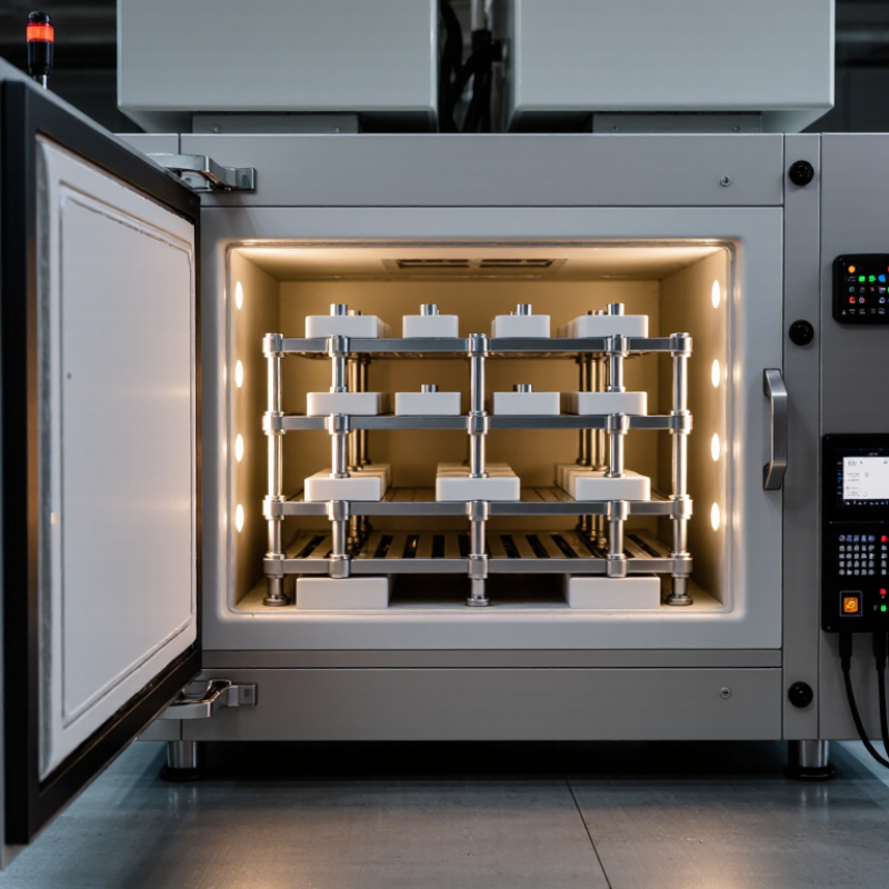
Before a vacuum-brazed assembly enters the furnace, mating surfaces are cleaned and aligned, then secured with a fixture that tolerates heat. The furnace door seals against a gasket, and pumps draw out air and moisture. Operators watch pressure gauges rather than relying on elapsed time alone; trapped oils or damp insulation can slow pump-down and contaminate the hot zone. The target vacuum depends on the alloy, joint design, and equipment, so one number cannot suit every job. Small detail, big consequence.

Once pressure is suitable, heating usually proceeds in controlled stages. A slow ramp helps the parts and fixture warm more evenly and gives residual gases time to escape. Thermocouples near representative joints help confirm the assembly—not just the furnace wall—has reached the required brazing range. At that temperature, filler metal melts and is drawn through the narrow joint gap by capillary action, while the parent metals remain solid. The hold must be long enough for flow, but excessive heat can encourage erosion or unwanted reactions. Vacuum alone is not a cure-all; poor fit-up still makes a weak joint. In practice, this sequence is rarely perfectly tidy. A load may need adjustment after a trial run, and that is useful evidence, not failure.

How Does the Vacuum Brazing Process Work? - Evacuating the Furnace and Heating the Assembly

Process stage What happens Typical controls or conditions Why it matters
Load and seal the furnace The cleaned parts, braze filler, and fixtures are placed in the furnace, which is then closed. Parts should be dry and free of oil, grease, and heavy surface contamination. Joint clearance and filler placement are set for the specific materials and design. Contamination can outgas during heating or interfere with wetting and joint formation.
Evacuate the chamber Vacuum pumps remove air and moisture from the furnace before the assembly reaches brazing temperature. The required vacuum depends on the alloy, materials, furnace, and cleanliness requirements. High-vacuum cycles may use pressures around 10-4 to 10-5 mbar; these are illustrative, not universal specifications. Reducing oxygen and other residual gases helps limit oxidation and supports clean, reliable brazed joints.
Check vacuum and outgassing The furnace may be held at a lower temperature while gases released from the load are removed. Operators monitor chamber pressure and follow the qualified cycle. A pressure rise can indicate outgassing or a leak and may require investigation. Heating too quickly before adequate evacuation can leave contaminants in the chamber or on the parts.
Heat the assembly Heating elements raise the temperature of the parts and filler according to a programmed cycle, usually while the chamber remains evacuated. Ramp rate and soak stages are set for the load, materials, and furnace. The cycle must account for thermal mass and temperature uniformity. Controlled heating reduces thermal gradients and helps the joint reach brazing temperature consistently.
Reach brazing temperature The filler metal melts and flows into the joint by capillary action, provided the joint surfaces are suitable and properly fitted. The temperature is selected from the filler alloy’s specified brazing range. It is generally above the filler’s liquidus temperature but below the base metals’ melting temperatures. The correct temperature allows filler flow and bonding while avoiding damage or excessive melting of the base materials.
Hold and cool The assembly is held for the qualified time, then cooled in the furnace under vacuum or a specified protective atmosphere. Hold time and cooling conditions vary by joint design, filler, and load. The chamber is usually vented only after the load has cooled to the procedure’s specified temperature. Controlled cooling helps protect the hot assembly from oxidation and limits unwanted thermal stress.
Inspect the brazed assembly After unloading, the joint is checked using inspection methods appropriate to its design and service requirements. Inspection may include visual examination, dimensional checks, or nondestructive testing when specified. Verification helps confirm that the cycle produced an acceptable joint and that the assembly meets its requirements.

Note: Actual vacuum levels, temperatures, hold times, and cooling procedures must be established for the specific materials, filler alloy, furnace, and approved process specification.

Melting the Filler and Forming the Joint

In vacuum brazing, the filler metal is positioned where two clean components meet. It may come as a thin foil, wire, or preformed ring. The parts need a close, even fit. Gaps that are too wide can leave weak or incomplete areas; gaps that are too tight may restrict filler flow. Small details matter.

The furnace heats the assembly in a controlled vacuum. As the temperature rises, the filler melts while the base metals remain solid. That distinction is essential. The liquid filler wets the prepared surfaces and flows into the joint by capillary action. A continuous, silvery line may appear at the seam, though appearance alone cannot confirm joint quality. Heat, filler choice, surface condition, and clearance all affect the result. There is no single setting that suits every material combination.

Then the assembly cools under controlled conditions. The filler solidifies and bonds the components without melting their main bodies. In practice, uneven heating or poor part alignment can disrupt flow. A joint may look neat yet still contain voids, so inspection and process records matter. It is easy to assume vacuum solves every surface problem. It does not; parts still need careful cleaning and preparation.

Cooling the Assembly and Inspecting the Joint

When the brazing cycle ends, keep the assembly under vacuum or an inert atmosphere while it cools. This limits oxidation before the filler metal solidifies. Use the qualified cooling rate for the specific alloys, joint geometry, and furnace load; a thick fixture cools differently from a thin coupon. There is no universal ramp. Record the furnace thermocouple trace, and avoid opening the chamber while hot. Rapid cooling can increase residual stress or distortion, while an unnecessarily slow cycle adds time without guaranteeing a better joint.

Inspect only after the part reaches a safe handling temperature. Check for warping, incomplete filler flow, surface cracks, and discoloration around the joint. AWS’s Brazing Handbook gives a typical joint-clearance range of 0.001–0.005 inch for many applications, but the correct gap depends on the materials and filler metal. A neat fillet is not proof of a sound interior. Use penetrant examination when surface-breaking defects matter; ASTM E1417/E1417M sets controls for that method, but it cannot reveal every internal void. For critical assemblies, section a representative sample and examine the joint under magnification. That takes time. It can also expose a cooling problem that visual checks miss.